Artificial Intelligence Notice: ISA prohibits the entry of ISA standards and related ISA intellectual property (“ISA IP”) into any form of Artificial Intelligence (AI) tools, such as ChatGPT. Additionally, creating derivatives of ISA IP using AI is also prohibited without express written permission from ISA’s CEO. In the case of such use, ISA will suspend a licensee’s access to ISA IP, and further legal action will be considered. Please review ISA's Terms and Conditions for further information.
Every plant in the process industry most likely has several control loops that do not perform well. Although there are many factors that may negatively affect control loop performance, a few of these factors are most common. With some skill and knowledge, it is reasonably easy to identify which of these common factors is the root cause of poor control loop performance.
With closed-loop control, poor performance typically manifests itself as deviations from set point. By analyzing these deviations, one can determine if they are caused by suboptimal controller tuning settings, a poorly performing control valve, insufficient filtering of the measurement signal, or simply process disturbances where the frequency and magnitude exceed the regulatory capabilities of a control loop. The diagram (figure 1) can be used as a troubleshooting tool to help determine the root cause of poor control loop performance.
Much of the troubleshooting that follows requires looking at process trends. Normally these are time trends of the process variable (PV), set point (SP), and controller output (CO). The time span of the trends depends on the dynamic nature of the process-fast-responding processes, such as flow and liquid pressure, require only a few minutes of data for proper analysis, while slow-responding processes may require data spanning several hours. Control systems have built-in or add-on process historians that can be used for viewing process trends.
Figure 1. Troubleshooting the root cause of poor control loop performance.
Oscillations
The first step in troubleshooting poor control is to determine if the deviations of the PV from its SP are random or cyclical in nature. With cyclical deviations, or oscillations, the PV peaks at fairly regular intervals. Random deviations do not have this regularity (figure 2). A visual inspection of the PV trend is all that is required to make this determination.
Once it has been determined that the control loop is oscillating, one should determine the origin of the oscillation. A control loop can be causing its own oscillation, or it could be affected by an interacting oscillation somewhere else in the process. A simple way to determine if the origin of the oscillation lies within the control loop or has an external source is to put the control loop in manual to see if the oscillation stops or continues. If the oscillation continues, it is likely caused by an external source. The exception here is if the control valve's positioner oscillates by itself. This can be determined by leaving the controller in manual mode, going out to the valve in the field, and seeing if the valve stem is oscillating.
Figure 2. Oscillations (top trend) versus random deviations (bottom trend).
An external source of oscillation could affect a control loop through the process or via the SP (if the latter is generated by another controller). This determination can be made by looking at a trend of the SP. It should be easy to see if the SP oscillates. If the SP is oscillating, the control loop generating the set point should be checked, as described later.
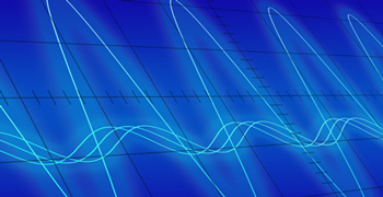
If the oscillation is coming from the process, a bit more detective work is needed. Trends of all the possible interacting process variables need to be inspected. With highly interactive processes, several control loops may be oscillating at the same frequency. The root cause of multiple oscillations can normally be found by looking at the trends to see which one of them peaks first. This can also be combined with looking at which signal has the least distortion (the crispest or cleanest oscillation, such as the triangular wave in figure 3). The oscillation leading the others and having the least distortion is most likely the cause of all the other oscillations. One can then troubleshoot the source of oscillation further, as described below.
Figure 3. The triangular wave (middle trend) leads the other oscillations and has the least distortion.
Once the exact loop causing the oscillation has been identified, the root cause can be determined through a few simple steps. The oscillation can have one of two causes: incorrect tuning or a control valve problem. If the control loop is oscillating because of tuning, trends of the PV and CO are normally smooth sine waves (except if the CO runs into upper or lower limits). If a control valve problem is causing the oscillation, a trend of the CO more closely resembles a triangular wave, while the PV more closely resembles a square wave (figure 4). Control valve stiction is a common cause of control loop oscillations, and being a valve problem, it needs to be addressed through control valve maintenance or positioner tuning. When incorrect tuning settings cause a control loop to oscillate, the PID controller needs to be tuned again, preferably by using a scientific tuning method, not trial and error.
Another scenario to consider is when two or more closely coupled control loops cause each other to oscillate. For example, if a pressure-reducing control loop is closely followed in the process by a flow control loop, the two control loops can appear to be fighting each other, causing both loops to oscillate. If either one of the controllers is put in manual, both control loops cease to oscillate. In this case, the most important control loop needs to be tuned for a fast response, and the other loop tuned to respond three to five times slower. The lambda tuning method lends itself well to tuning the second loop for a slow response.
Figure 4. Control loop oscillation caused by stiction.
Random deviations
Now on to the case in which the PV deviates from its SP in a random (nonoscillatory) fashion. If the deviations occur very rapidly, much faster than the control loop can respond, the deviations can be considered to be noise. The best solution for PV noise is to apply a small filter, such as a first-order lag filter, to the signal. Note that a filter changes the dynamics of the control loop, and consequently the controller has to be tuned again.
If the deviations are too slow in nature to be considered noise, a filter should not be applied. Because the PV deviates relatively slowly from its SP, the controller may seem to respond to it too slowly, allowing large deviations before gaining control over the process. This is likely a result of sluggish tuning, which calls for the controller to be tuned again for a faster response if possible (as explained later).
Note that deadband in the control valve may create the appearance of the controller responding sluggishly. It takes a while for the controller to traverse the deadband before the control valve actually starts responding and affecting the process. In this case, controller tuning is not the right solution for the problem, since deadband is a mechanical issue with the control valve. The presence of deadband in a control valve can be determined by putting the controller in manual mode and making two CO changes in one direction, and a third change in the opposite direction. Make the second and final steps equal in size and wait for the PV to settle out after every step. If, after the final step, the PV does not return to the same value as after the first step, deadband exists in the control valve (figure 5).
Also realize that every control loop has a limit on its speed of response. If this limit is exceeded by tuning the controller for too fast of a response, the control loop will become unstable and oscillate. Best practices for controller tuning recommends leaving a healthy margin away from the stability limit. If a controller has been tuned properly, and deviations of PV from the SP are still excessive, it may be the result of the disturbances being too severe to be handled solely by feedback control. Depending on the cause of the disturbance, adding cascade, feedforward, or ratio control to the control design could make a significant improvement.
Figure 5. Control valve deadband test.
Reader Feedback
We want to hear from you! Please send us your comments and questions about this topic to InTechmagazine@isa.org.
Jacques Smuts, PhD, PE, is the founder and principal consultant of OptiControls, Inc. He has more than 25 years of experience in process control and is the author of the book Process Control for Practitioners.